After test driving the Mkrfox 1200 Arduino with Sigfox functionality on board and giving an introduction to programming in the previous two parts it’s time now to have a closer look at some of the basic parameters of a Sigfox network to get an idea of the capabilities and constraints, what that means for devices and applications using the network.
Uplink Channel, Bandwidth and Transmission Power
![]() In Europe, Sigfox uses a few kHz of unlicensed spectrum around 868 MHz for uplink transmissions. Sigfox devices transmit with a data rate of 100 bit/s. Yes, you read correctly, not Gbit/s, not MBit/s or kbit/s, it’s 0.1 kbit/s with a channel bandwidth of 100 Hz. Compare that to the 200.000 Hz (200 kHz) bandwidth of a GSM carrier and you get an idea of just how super narrow band the signal is! As Sigfox uses unlicensed spectrum, transmission power is limited to 25 mW as indicated in the screenshot above which shows an excerpt from a table in the Wikipedia page on license free bands for short range devices. Again, compare this to the 2000 mW that a GSM device can transmit its bursts with on the 900 MHz band and you get an idea of how ‘downsized’ this technology is to optimize for very low data rates and very low power consumption. Obviously, being limited to 25 mW of transmit power also limits the reach of the signal. This is offset to some degree by focusing the available power to a 100 Hz channel while GSM spreads its 2W transmit power over a 200 kHz channel.
In Europe, Sigfox uses a few kHz of unlicensed spectrum around 868 MHz for uplink transmissions. Sigfox devices transmit with a data rate of 100 bit/s. Yes, you read correctly, not Gbit/s, not MBit/s or kbit/s, it’s 0.1 kbit/s with a channel bandwidth of 100 Hz. Compare that to the 200.000 Hz (200 kHz) bandwidth of a GSM carrier and you get an idea of just how super narrow band the signal is! As Sigfox uses unlicensed spectrum, transmission power is limited to 25 mW as indicated in the screenshot above which shows an excerpt from a table in the Wikipedia page on license free bands for short range devices. Again, compare this to the 2000 mW that a GSM device can transmit its bursts with on the 900 MHz band and you get an idea of how ‘downsized’ this technology is to optimize for very low data rates and very low power consumption. Obviously, being limited to 25 mW of transmit power also limits the reach of the signal. This is offset to some degree by focusing the available power to a 100 Hz channel while GSM spreads its 2W transmit power over a 200 kHz channel.
Sigfox Uplink Messages
This page on the Signal Identification Wiki has a screenshot and further details on how a Sigfox message looks like in a ‘waterfall’ diagram where the y-axis represents time and the x-axis frequency. Each Sigfox message has a length of up to 26 bytes and can contain up to 12 bytes of user data. This is the reason why the Sigfox ‘send message’ function on the Arduino only accepts up to 12 bytes of data. Each Sigfox message is repeated 3 times on three different and randomly selected 100 Hz chunks of the overall channel as described on the Sigfox Technology introduction pages. This is also shown very nicely in the waterfall diagram linked to above. At a transmission speed of 100 bits per second, which equals 12.5 bytes per second, a 12 bytes user data message takes around 6.25 seconds plus some time for the gaps between the three transmissions.
Why Limit the Number of Uplink Messages to 140 Per Day?
The Arduino board comes with a 2 year network subscription included that limits the number of messages to 140 per day. It’s a bit of an odd number so I was wondering for a while why it’s not 100, 150 or 200 messages a day. The answer lies perhaps the 1% duty cycle which license free devices have to observe at 868 MHz (see table entry above). The day has 86400 seconds so a device must not occupy the channel for more then 864 seconds per day. Now divide the 864 seconds by the 6.25 seconds required to send a message and you end up with…. 138,24 messages/day.
Uplink and Downlink are Independent
Another thing that sets Sigfox apart from other cellular technologies like GSM, GPRS, UMTS, LTE, NB-IoT, etc. is that there is no synchronization of uplink and downlink. Very simple Sigfox modules don’t even have a receiver so they can’t even tell if a Sigfox network is present which could receive their uplink messages. In other words, uplink messages from a Sigfox device to the network are sent blindly and there is no feedback on the radio layer from the network to the device if a message has been properly received or not.
Due to the transmit-only nature of the system it is not ensured that several devices do not transmit on the same frequency simultaneously. Statistically, however, this is very unlikely due to the very narrow channel bandwidth of 100 Hz compared to the total available bandwidth and the very infrequent transmission of data by each device. Obviously, the chance of devices interfering with each other increases as more and more devices are used in the same cell but I haven’t come across a number at which point this will become critical.
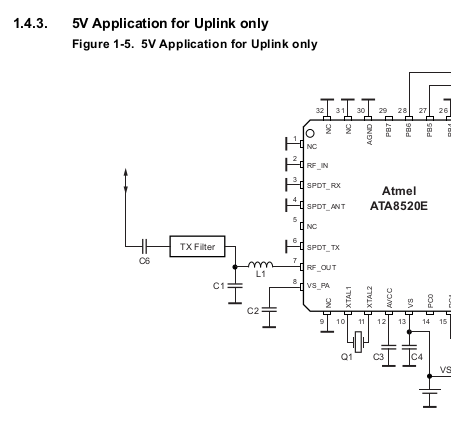
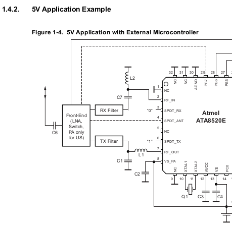 While simple Sigfox chips are transmit-only devices, the Mkrfox 1200 Arduino board uses the Atmel ATA 8520 with a transceiver front end for bi-directional communication. Devices that only want to transmit data without receiving feedback it’s also possible to use a much simpler TX front end with the chip. The two figures on the left taken from the ATA 8520’s data sheet show the two options.
Obviously, compared to other cellular systems where the network controls access to the network, Sigfox device hardware and software can be much simpler and power efficient. The downsides are, however, that the network can’t control access to the network, it can’t acknowledge proper reception, organize retransmissions, instruct a device to use additional redundancy to compensate for bad signal conditions, enforce priorities, etc. In many cases this won’t be necessary but it limits the type of applications for which Sigfox is suitable.
Downlink Messages
![]()
Many IoT applications require that a device can also receive data, e.g. for reconfiguration purposes. Sigfox can transmit up to 8 bytes in a downlink message and limits the number of downlink messages to 4 per day. In other words, 32 bytes of information can be sent to the device per day if the limit is enforced. For most configuration data this should be an ample amount but software updates are obviously not an option. Perhaps that’s not even a bad thing as this makes it even harder to maliciously hack the device over the air.
For the downlink direction, Sigfox uses the license free 869.4 to 869.65 MHz frequency range with a maximum transmission power of 0.5W and a maximum duty cycle of 10%. In other words, a Sigfox base station must not transmit data to devices more than 10% of the time. While 500 mW is much more than the 25 mW that devices are limited to, it is still not much when compared to GSM or LTE base stations that use a transmission power in the order of 20 watts per channel. Compared to those channels the channel required for a downlink data rate of 600 bit/s is again very narrow which compensates to some degree for the comparatively much lower power.
Listening Times For Downlink Data
Another important restriction to reduce power consumption as much as possible on the mobile device’s side is that they are only required to listen for incoming data for 30 seconds after an uplink transmission. After that the Sigfox chip goes back to sleep and will not be able to detect incoming messages. In addition, due to the 10% duty cycle the base station has to observe downlink data has to sometimes be buffered for a while before it can be transmitted. In practice that means that a server on the Internet can’t contact the device at any time but has to wait until it receives a message and then has to send a response message within a few seconds. While responding quickly is usually not a problem, having to wait until the device sends a message on its own also limits the kind of applications that the network is suitable for.
The Long Wait
I actually have a practical example where having to wait for a response for half a minute because of the 7 seconds it takes to send the uplink message, the time it takes for the downlink message to be transmitted and to observe the 10% duty cycle at the base station side is a major show stopper. I live in Cologne where a company offers bike rentals. If I want to rent a bike I have to waive my customer card over an NFC reader after which the bike’s rental computer communicates to the back end server. If the server gives the go-ahead, the lock is opened and I can use the bike. When I arrive at the destination I have to lock the bike again which triggers another communication session with server to indicate its location and availability status. In both cases I have to wait for at least half a minute before the bike becomes available to me or before I get the information from the display that the rental return was successful. This is an awfully long time and a major pain point. Perhaps they are using Sigfox for communication because the delay very much reminds me of the time I have to wait for a downlink message with my Arduino board after I’ve sent an uplink message.
Sensitivity
I was hoping that the very narrow channels would sufficiently offset the very low signal power Sigfox is restricted to because of the use of unlicensed spectrum. I was quite disappointed in that regard however. While most uplink messages were properly received on the network side while I was outside or very close to a window, transmissions were usually not picked up by the network when I used the device in normal indoor scenarios where mobile phones still have very good reception. Also, messages my module sent while I was on my daily commute in the train or my car were also not picked up. Receiving downlink messages seems to be even more difficult in practice. In most places were I could send messages I could not receive downlink messages from the network. At first I thought that perhaps the transmit power of the Mkrfox board is too low. So I connected it to a spectrum analyzer reported an observed transmission power of 12.5 to 14 dBm depending on the setup. This looks quite o.k. as 14 dBm is pretty close to the 25 mW maximum allowed in the band. I also tried different antennas but the result would also not change. So everything seems to be all right on the device side.
International Use
Another interesting Sigfox feature is that once a device is activated it will work in any country a Sigfox network has been rolled out in the frequency band the device supports. I tried this out in practice while I was in Belgium over a weekend and can confirm that this works. This is a major advantage compared to other cellular technologies where networks are operated by independent companies. To roam internationally, other networks must be interconnected and operators usually charge each other and their customers for international roaming.
Unfortunately, Sigfox has to use different bands in Europe and the US so global connectivity is not assured. Perhaps we will see ‘multi-band’ Sigfox modules in the future for global connectivity. I wonder a bit however, how the device can then detect which frequency band it is supposed to use as a device does not search for a network before it transmits its messages.
Summary
After playing with Sigfox for some time I have to say that I was very impressed by how little effort is required to prototype an Arduino IoT application and that only a single function call is required to send a message over the Sigfox network to a server on the Internet. The limited indoor coverage I experienced in Cologne and the inherently long round trip time for receiving a response from the server are probably not an issue for many IoT applications but one should be aware of these limitations at the beginning of a project.