The LTE air interface uses Orthogonal Frequency Division Multiplexing (OFDM) to transmit many slow data streams (1200 in a 20 MHz carrier) in parallel to achieve a very high overall speed. OFDM is not exclusive to LTE, it is used in many other systems such as Wifi and DSL as well. For more details have a look at this post from back in 2007. One thing not contained in that earlier post is how each of the 1200 slow data streams is actually transmitted. In good signal conditions 64QAM is used in the LTE downlink direction. So what is 64QAM and how does it work?
QAM stands for Quadrature Amplitude Modulation and is a modulation technique that encodes several bits per transmission step in the amplitude of a sine wave signal and, in addition, in a phase shift compared to a reference signal. In other words the bits are encoded in two dimensions.
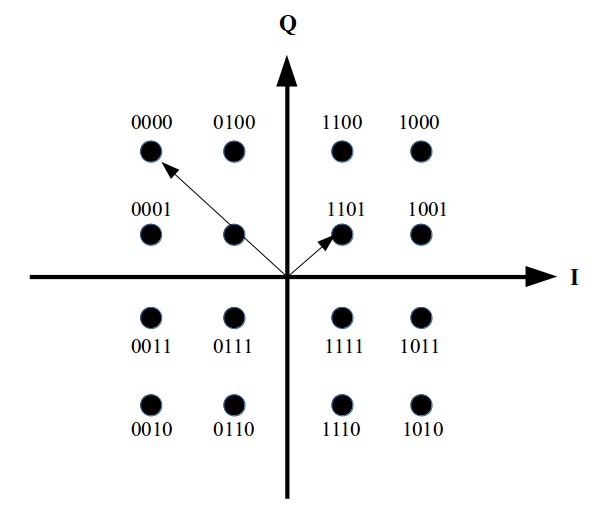
From a mathematical point of view the two dimensions can be expressed as a complex number with an I- and a Q-component. The following image shows how bits are encoded in I and Q in a Cartesian coordinate system. Each point on this grid represents 4 bits and has an I-amplitude and a Q-amplitude associated to it. In total there are 16 combinations, hence this is 16QAM modulation.
 In a time based signal these amplitudes are represented as follows:
The point representing 1101 has an I-amplitude of +1 and a Q-amplitude of +1. This means that this point is represented in a time signal by a wave with an amplitude represented by the length of the arrow and a phase shift of 45 degrees compared to an unaltered reference signal.
The point representing 0000 has an I-amplitude of -3 and a Q-amplitude of +3. In a time signal this is expressed as an amplitude represented by the length of the arrow from the center of the grid to this point and a phase shift of 135 degrees compared to a reference signal.
From a mathematical point of view it can be shown that the amplitude and phase of a sine wave can be changed by generating it out of two sine waves oscillating at the same frequency. The difference between the two signals is that the one of the signals is phase shifted by exactly 90 degrees compared to the other. This means that one of the sine waves passes through 0 on the x axis 1/4 (a quarter, quadrature…) of the wave earlier than the other signal. In such a setup the amplitude and phase of the resulting signal is then controlled by only changing the amplitudes of the two input signals.
The amplitude of one of the two input sine waves represents the I-component of the signal, the other one the Q-component. In other words, the I- and Q-amplitudes from the diagram for one of the points are then used during each transmission step to set the amplitude of each signal.
On the receiver side the same operation is performed in reverse, i.e. the amplitude and phase encoded single input signal is given to two processing chains and each recovers one of the amplitudes that was used at the transmitter side.
Fun fact: The I- and the Q-signals are also referred to as the ‘baseband’ signals. This might ring a bell because the LTE modem chip is also referred to as ‘the baseband’, as it sends and receives these baseband signals to and from analog components that sit in between the baseband chip and the antennas.
If this was all a bit quick, have a look at this really great video over on YouTube by W2AEW.