 In the first part of this series, I emphasized that in 3GPP Release 15, a major focus is to get a first incarnation of 5G into the field that complements 4G LTE. Instead of today’s approach where a device is either connected to GSM, or to UMTS or to LTE, i.e. only to one technology at a time, things will be different in 5G. Due to the higher frequencies bands used and other reasons (see part 1) it was deemed better to enable mobile devices to connect to LTE and 5G New Radio (NR) simultaneously. This is referred to as Dual Connectivity EN-DC. So how will this work in practice?
EN-DC!?
So let’s first have a look at the acronym. EN-DC stands for ‘E-UTRAN New Radio – Dual Connectivity’. E-UTRAN is of course LTE in everyday speak and New Radio (NR) is the 5G radio network. The way simultaneous LTE and NR connectivity will work is described a bit off the beaten path in 3GPP TS 37.340 which deals exclusively with E-UTRAN and NR multi-connectivity (note: the word ‘multi’ does not limit connectivity to 2 like ‘dual’ does…). The specification describes a number of different options for multi-connectivity but I will only look at LTE/NR dual connectivity with a ‘traditional’ LTE core network. I think it is likely that such a configuration will be deployed in practice first, followed, perhaps a few years down the line, with a configuration that includes a 5G core network.
EN-DC with an LTE Core Network
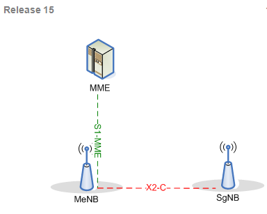
Having said all of this lets have a closer look at two diagrams from TS 37.340 included in this post. The first one above shows the EN-DC control (C-) plane. Those of you familiar with LTE will immediately recognize the LTE core network control node, the MME (Mobility Management Entity). The MME exclusively communicates to the LTE base station, the eNodeB (eNB), and is not concerned at all with the 5G base station, the gNB. As said above, there is no 5G core network! In the diagram, the base stations have slightly different names. The LTE eNB is referred to as the MeNB to indicate that it is the ‘Master’ (M) base station controlling the ‘Secondary’ (S) 5G NR base station. The S1 and X2 interfaces are also already known from LTE.
 The second diagram shows how user data, i.e. IP packets, flow between the base stations and the core network. Again the S1 interface is used for the purpose. In the diagram, both the MeNB and the SgNB have an S1-U (User) interface. For transferring data to a single user, however, only one S1-U connection is used. In other words, the data for a user is either exchanged between the LTE Serving-Gateway (S-GW) and the LTE base station or with the NR base station but not with both at the same time! Let’s say the user data is exchanged by the S-GW with the 5G SgNB and the UE exchanges user data with the SgNB and the MeNB simultaneously which is the whole point of EN-DC. In this scenario, the 5G SgNB forwards a part of the user data stream that arrives from the core network via the X2 (-U) interface to the MeNB. This concept is also referred to as a ‘split bearer’ and, as an interesting side note, was already introduced in 3GPP Release 12 but never really used to transmit data simultaneously from an LTE macro and LTE small cell that are interconnected over a ‘non-ideal’ backhaul. Its important to note a split bearer is not that same as LTE carrier aggregation because the air interface schedulers in the MeNB and SgNB are independent of each other and can decide on their own when and how their share of data is transferred.
Dual-Connectivity Setup
While the transfer of data is split between LTE and NR, control of dual-connectivity is always in the hands of the eNB. When a mobile device wants to exchange data with the network it establishes a connection with the LTE network. If the eNB has an ‘integrated’ gNB and if the mobile device indicates support for EN-DC on the frequency band the gNB is operated on, the LTE eNB will instruct the mobile device to make measurements on the NR channel. If a signal is found the eNB will then communicate to the gNB and give it all necessary parameters to establish a connection to the mobile device as well. Once the gNB confirms the connection setup, the eNB will then forward a part of the incoming user data the the 5G gNB for transmission to the mobile. Optionally, the eNB can then ask the core network S-GW to directly exchange user data with the gNB. In this case the gNB will then forward a part of the user data to the eNB. The signaling flows of this scenario and also for other important scenarios such as handovers due to user mobility can also be found in TS 37.340. Have a look there if you are interested in further details.
Single RAN Thoughts
Before closing for today there is one more point I would like to make on why this kind of dual-connectivity is easier to achieve as it would have been 10 years ago with 3G and 4G. Back then LTE hardware and software especially at the base station site was completely separate, hence, communication between the 3G NodeB and 4G eNodeB would have been quite difficult. Fast forward to today and things in the radio network are quite different. Most network operators that are interested in 5G have switched to a ‘single-RAN’ infrastructure. This means that at the base station site, the RF and digital modules run the 2G GSM, 3G UMTS, 4G LTE and, in the future, 5G NR software at the same time on the same physical hardware. In other words, the X2 interface between the eNB and the gNB is likely to be virtual rather than physical.
Oh yes, and there is one more thing: Directly connecting a 5G gNB to a 4G core network is referred to in the specifications as Non-Standalone Architecture (NSA) vs. a standalone architecture (SA) that requires a 5G core network to be in place. NSA!? I wonder who came up with this acronym which most people associate with something quite different…
There’s also FS_NSA, the feasibility study for New Security Architecture in 3GPP 😉