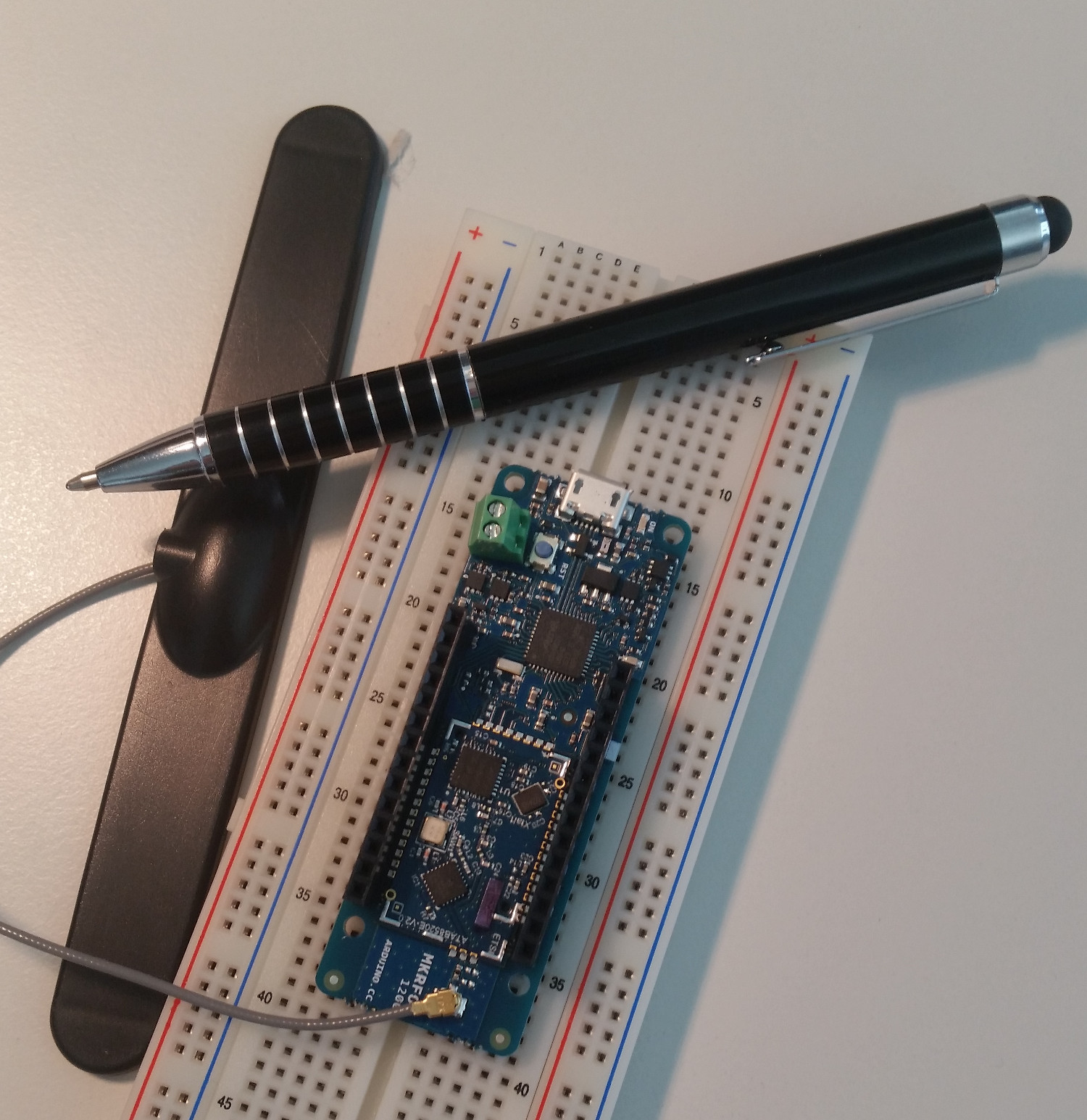
 After reading about the MKRFOX 1200 Arduino with built in Sigfox connectivity and a 2 year subscription for 50 Euros (including VAT and shipping), I ordered one right away and was pleasantly surprised that it arrived only a few days later. This and the following posts document my first impressions and give a basic overview of Sigfox devices, the network, the back end server and their capabilities.
Why Is This Significant?
As I wrote in my earlier post I think this board is significant as it offers a cheap and in every aspect easy way to experiment with an Internet of Things (IoT) device that can communicate over a cellular network rather than using local short range connectivity such as Bluetooth or Zigbee. Things are easy because the Arduino PC software for Linux, Windows and the Mac is straight forward to install and use and the board comes with a 2 year network access subscription for 140 uplink and 4 downlink messages per day.
Initial Setup and Blink’n Lights
Never having worked with Arduinos before it nevertheless only took me about half an hour before I could send my first message to the Sigfox network and from there to me.
In a first step I downloaded and installed the standard Arduino development environment on my Ubuntu machine as described here which communicates with the Mkrfox board over USB. No other cables are required, power is supplied over USB as well during development. Once done one more thing that needs to be installed before the first ‘hello world’ program can be compiled and downloaded is the board support package. This is a simple click to install exercise in the development environment as described here. After that the standard test program that makes the on-board LED blink can be downloaded right way without any further ado.
Getting Sigfox Functionality Up and Running
The next and final configuration step, as far as the Mkrfox board is concerned, is to install the Sigfox, LowPower and RTCZero software libraries with a few clicks in the development environment as these are required by the Sigfox demo program. Once done, a first Sigfox send message program can be copied from here and pasted into a new “Sketch” in the development environment. A single click compiles, downloads and executes the program to the board and the debug text console window then shows the Sigfox ID of the board which is needed to register to the Sigfox portal. Afterward the program waits for user input which is sent as a Sigfox message after pressing enter. In the program, the Sigfox debug mode is activated which makes the status LED on the board blink during data transmission which is quite helpful to get a visual indication indication when something is transmitted.
How To Get Messages That Are Sent?
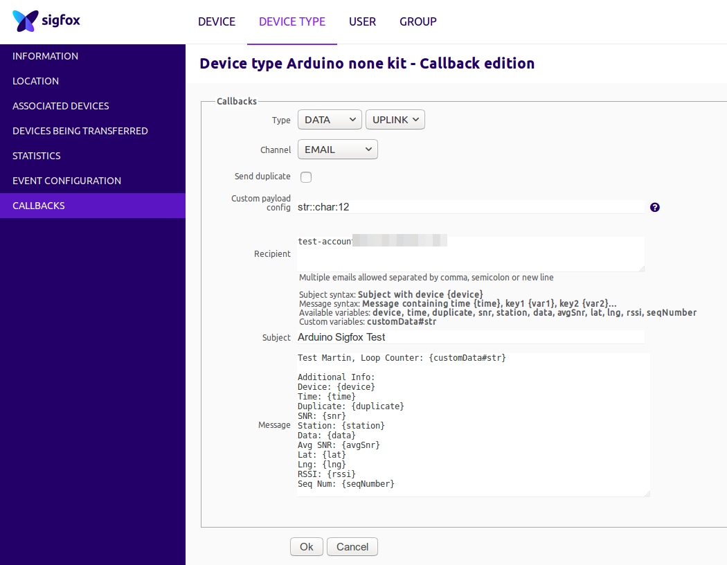 As Sigfox is not an IP based technology, it is not possible to directly send a message to a server on the Internet. Instead the Sigfox base stations forward received messages to a centralized back end server on which actions can be configured for individual or groups of Sigfox devices. After registering the Sigfox device with its device ID on the Sigfox back end server, it offers options to forward incoming messages via email, HTTP GET or POST requests or as JSON encoded strings to Amazon’s and Microsoft’s IoT cloud platforms. I decided to go for the email option for a start as this is straight forward to set-up by simply specifying the email address, what kind of additional meta data to include and in which format. In addition to the message that was sent by the device the email can include things like a reception timestamp, sequence counter, base station ID, signal strength with which the message was received and other things. Here’s an example of how an email looks like for a single message after configuring email forwarding as shown in the second screenshot above:
Test Martin

Info:
Device: xxxxxx
Time: 1594230821
Duplicate: false
SNR: 6.08
Station: 0410
Data: 3139353030
Avg SNR: 22.18
Lat: 51.0
Lng: 7.0
RSSI: -138.00
Seq Num: 42
The actual message that was sent in the example above by the Mkrfox device was ‘3139353030’ which is the ASCII code for the number 19500.
And that’s it for this Sigfox primer. In the following parts I’ll have a closer look at how the Sigfox chip on the Mkrfox 1200 board can be used by programs running on the ARM Cortex M0 based microcontroller and how messages can be sent to the Sigfox device from a server on the network. Also, I’ll have a look at the basic characteristics of Sigfox data transmissions and at the reception limits of the air interface.
Thanks, it makes me want to order one as well. The frequency used, 868 MHz, would go through walls and potentially reach underground levels, I’m curious to test in my building, could use this to report temperature check without having to wire anything.