 Back in 2013 I finally managed to get hold of a Busch 2090, a historical microcomputer learning kit I always wanted as a teenager but couldn’t afford. Apart from its historical value to me it is still a great tool to learn and better understand how computers work. At the time, Busch also sold a separate tape interface board with which one could load and store programs to ordinary music cassettes which made experimenting with larger programs a lot easier. Unfortunately the Busch 2090 I bought didn’t have one and it is extremely rare to find one on eBay. While I didn’t particularly mind so far, I’m playing with the thought of participating at the VCFB 2017 in Berlin later this year where it would be great to have the ability to quickly load and demonstrate different programs. The more I thought about it the more I got interested and decided that instead of trying to buy the historical hardware I would find out if I could build a hardware emulator with a Raspberry Pi. This blog entry is part 1 of the story around that project. If you are interested in historical computing or reverse engineering an interface to build an emulator hardware and software for it, read on.
What I Had and What I Did Not Have
My starting point for building an emulator that connects to the Busch 2090 tape interface connector was not ideal. While I have a Busch 2090, the manuals for it, the manual for the 2095 tape drive interface and a good idea which signals connect to the pins of the tape drive interface connector on the board, I had no information about the protocol used whatsoever. Also I didn’t have the real 2095 tape drive interface board. In other words, there was no way I could record a real data transmission from the tape board to the microcomputer board with my Bitscope logic analyzer. That was obviously not much to start with.
To keep things as simple as possible I decided to focus on the digital part, i.e. the idea was to emulate the cassette tape and the tape interface card as a whole and to directly receive/send the digital data stream to the microprocessor board
LEDs Are Your Best Friends
In the tape drive manual I could find a good description of how reading and writing to tape worked in practice so I thought I’d start my investigation by first finding out if I could make the Busch 2090 send a program to the tape interface board. Based on this information I would then search for a way to write data from the simulated tape and tape interface to the microprocessor board.
The clue to my starting point came from the tape manual which said that the button on the interface board needs to be pressed to start the data transmission from the microprocessor board to the tape. As there are only 4 inputs on the 2090, I manually set each of them to HIGH and back to LOW again one at a time. When setting input 3 to high I noticed that one of the built-in LEDs on the output pins of the 2090 suddenly lighted up. Ah, so setting input 3 to HIGH for a short while seemed to trigger the start of the data transmission.
The Manual Way
The tape board manual further revealed that after each program instruction from memory was sent to the tape drive, the 7-segment display would light up for a short while and show the instruction that was sent. Unfortunately I didn’t see that yet so there must be more to it than just toggling input 3. After experimenting a bit more by setting the different inputs manually to HIGH with a wire I suddenly saw the 7-segment display light up for a split second just as described in the manual. Heureka! The exhilaration was short lived, however, because while I could reproduce the effect, I couldn’t yet reproduce it in a deterministic way.
After quite a bit of additional trial and error I noticed that I could get from one instruction to the next and to make the display light up for a split second each time by setting pin 4 to HIGH for a moment and to touch pin 2 afterward with my ‘HIGH’ wire. While pin 4 first, pin 2 second was a reproducible approach, the number of times I had to touch pin 2 with the ‘HIGH’ wire before the 7-segment display blinked, varied. I figured that this was perhaps caused by the signal bouncing between HIGH and LOW several times whenever I touched the input pin with the wire.
Bouncing Remedies
To get rid of the bouncing I brought the Raspberry Pi and its GPIO ports into play for the first time in the project to produce the required HIGH and LOW signals for input port 2, 3 and 4 and to observe the result on the 4 output ports of the Busch 2090 with my Bitscope. One additional problem that had to be overcome at this stage was that while the Raspberry Pi input and output ports work with 3.3V logic, the Busch 2090 board from back in 1981 uses 5V logic levels. At first I was hoping that 3.3V would still be detected as a HIGH but I quickly found out that this was not the case. So I needed a logic level converter.
Logic level converter chips are available on the market but I didn’t want to wait until I could get my hands on one so I was hoping that there would be another way. After a bit of research on the Internet I found a tip that today’s 4xxx logic chips when operated at 5V still detect 3.3V as a HIGH signal and set their outputs to 5V. I didn’t have a large store of logic chips at home but I could find a HEF4081 which implements four 2-way AND gates. By connecting both input pins of a gate to a Raspberry Pi GPIO pin I could get the proper 0V and 5V signal levels on the output I needed for the Busch on the 2090. Quick, cheap, perfect!
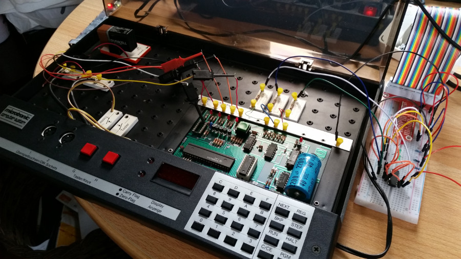
 As can be seen on the picture at the beginning of this post I quickly wired the chip on a breadboard to level-shift three signals from 3.3 to 5V and then wrote a short Python program for the Raspberry Pi to first send a short clock signal to input pin 3, then a short signal to input pin 4 and then several clock signals to pin 2 as described above. An instruction word of the Busch 2090 contains 3 nibbles of 4 bits each so I figured that toggling pin 2 for each bit should do the trick. And indeed when I ran the program, the 7-digit display indeed lit up for a split second. I then put the pin 4/2 interaction in a loop and to my delight I could see the 7-segment display light up after each loop and showing the next instruction data that was sent. Now that I had a stable procedure I put specific values such as 0xAAA, 0x555 and 0x123 into different instruction memory locations to observe with the Bitscope logic analyzer where the bits ended up on the output pins of the Busch 2090. It turned out that the bits are sent sequentially over output pin 1 as shown in the second screenshot on the left. In addition the 2090 board generates a clock signal on output pin 2 once at the start of the 12 bit transmission and sets pin 3 to HIGH for the duration of the complete transmission. Success!
![]() The third picture on the left shows how several 12 bit instructions are sent to the tape drive sequentially and how pin 2 and 3 signal the start and overall duration during each transmission. The individual bits on pin 1 can’t be seen here due to the low resolution, they are simply shown as a spike.
The third picture on the left shows how several 12 bit instructions are sent to the tape drive sequentially and how pin 2 and 3 signal the start and overall duration during each transmission. The individual bits on pin 1 can’t be seen here due to the low resolution, they are simply shown as a spike.
How Fast Can It Go?
The tape interface manual says that data is transmitted to the tape at a whooping speed of 14 baud per second. Yes, that’s 14 bits a second which is a tad more than 1 instruction per second. So is that the best the Busch 2090 can do? I played around with the timing of the signals to see where the limit is and I could push the transmission speed to around 70 Baud per second.
Procedure Summary
All of the above happened over several days as getting from one part to the next required some thinking and research. To make a long story short, here’s how the tape interface of the Busch 2090 works when data is sent from the microprocessor board to the tape interface board:
First, it is important to realize that all synchronization and trigger signals required for the transmission are sent from the 2095 tape drive board. It acts as a master that controls the process while the Busch 2090 microcomputer board acts as a slave device. After starting the ‘store to tape’ program on the 2090 (PGM2), it waits until it receives a HIGH signal on input pin 3 from the tape interface board. It then waits for a signal on input pin 4 to mark the start of the transmission of a 3x4bit value and then sends one bit on output pin 1 for each HIGH signal it receives on input pin 2. In addition output pins 3 and 4 are used by the microprocessor board to signal the start and overall duration of the data transmission of one 12 bit instruction. After transmitting all 12 bits of an instruction the Busch 2090 shows the instruction on the 7-segment display for a split second as described in the manual which is a great way to see that the Raspberry Pi tape emulator sends the right signals to the Busch 2090. The Busch 2090 then waits for another signal on input pin 4 to repeat the procedure for the next 3×4 bit instruction.
The Next Step
So far so good but the ultimate goal is not to save a program from the Busch 2090 to the tape drive but rather to emulate the tape drive so I can download programs into the Busch 2090. With some luck and the knowledge gained so far I should be able to make the reverse process work as well. More about this in part 2 of this story.
In the meantime have a look at my Busch 2090 Tape Drive Emulator repository on Codeberg if you want to find out more.
Nice!!! The 2095 is so rare – many Microtronic fans without a 2095 will *love* this. Not to mention how much easier it will be to enter Microtronic programs using a text editor on the Pi. Great work!